DC/DC converters testing
Below you can see the tables and plots from my tests of 3 dc/dc converters:
- MP8862
- MP28167
- AP63203
I wanted to compare the two MP… converters and see which one will be better to implement it in my power supply design.
On the other hand, AP63203 is a step-down converter for 3.3V 2A output current, that requires as little as 1 inductor and 4 capacitors to work correctly. That is why I needed to try it out when I saw it and based on the results of my tests, I can recommend it for any design requiring low voltage supply for microcontrollers etc, when the LDO would be wasting too much power and you still want to keep the cost and size to the minimum.
Test equipment
For my tests I used a lab power supply, with 10mA current resolution and a constant current load with 1mA, 10mV accuracy.
MP8862 test
Arduino code
In order to change the output voltage of the MP8862 converter you have to write a 12-bit value to two registers of the iC via I2C. For that purpose I used an Arduino Uno with the code below:
void setup()
{
  Wire.begin();
  Serial.begin(9600);
}

void loop()
{
  if(Serial.available())
  {
    String input;
    input = Serial.readStringUntil('\n'); //get data from the serial port
    int voltage_set = input.toInt();

    Serial.println(voltage_set);

    voltage_set = voltage_set * 100; //1V = 100 * 10mV

    uint8_t voltage_lower = voltage_set & 0b00000111; //last 3 bits
    uint8_t voltage_higher = (voltage_set >> 3) & 0xFF; //first 8 bits

    Serial.println(voltage_lower);
    Serial.println(voltage_higher);

    Wire.beginTransmission(107); // transmit to device addr
    Wire.write(byte(0x00));        //register for setting the voltage
    Wire.write(byte(voltage_lower));              // voltage  (lower 3 bits of 11)
    Wire.endTransmission();    // stop transmitting

    delay(50);

    Wire.beginTransmission(107); // transmit to device addr
    Wire.write(byte(0x01));        //register for setting the voltage
    Wire.write(byte(voltage_higher));              // voltage  (highest 8 bits of 11)
    Wire.endTransmission();    // stop transmitting

    delay(50);

    Wire.beginTransmission(107); // transmit to device addr
    Wire.write(byte(0x02));        //register for writing the output GO bit
    Wire.write(byte(0x01));              // turn on
    Wire.endTransmission();    // stop transmitting
  }
}
First, you setup the I2C connection and serial (USB). Then the program waits in the loop for user input through the serial terminal. In there you can put the desired output voltage and confirm with enter. After receiving the voltage it gets translated into the seperate bytes for two registers. After that, we write those two values to the I2C bus following the frame format from the MP8862 datasheet and go back to reading the input.
Test results
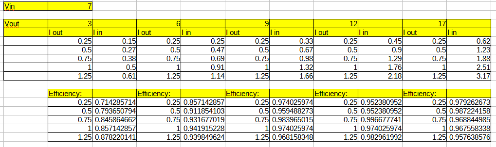
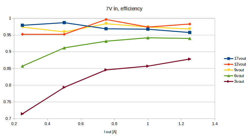
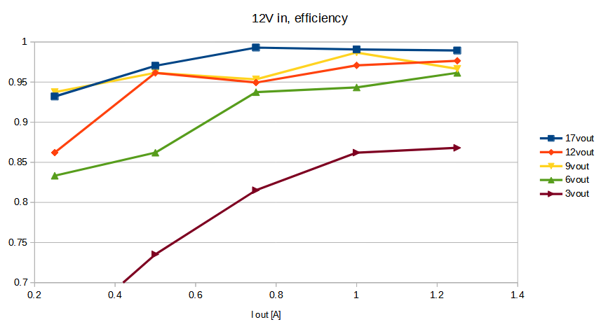
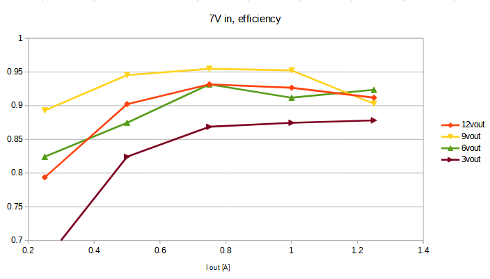
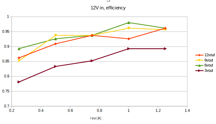
I tested the MP8862 with two different input voltages: 7V and 12V because those are the lowest and highest voltages I have in the design in which I plan on using it. The output current was in the range from 0.25A to 1.25A.
MP8862 test
Arduino code
The only differences in the code are:
- different I2C address:
Wire.beginTransmission(96); // transmit to device addr
- different way of calculating the output voltage:
voltage_set = voltage_set * 800 / (1 + 430000/53600); //430k and 53.6k resistors for feedback
Test results
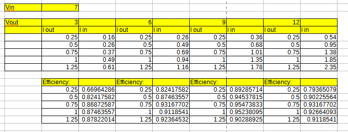
The results were very close to the MP8862, which is to be expected as both of them probably use the same internal circuitry. The only difference is the way we can set the output voltage, with MP28167 giving us the possibility to manipulate the reference voltage level. Once again the converter seems to work much better as a boost converter than a step-down.
AD63203 test
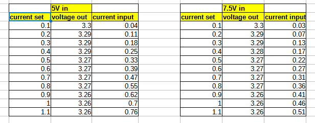
In here you can see the results of testing the converter for 4 different input voltages: 5, 7.5, 10, 12V and current ranging from 0.1 to 1.1A
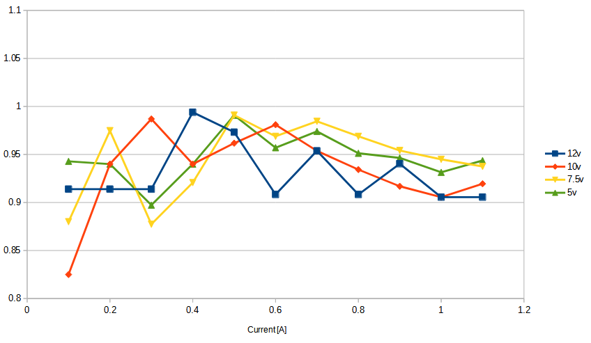
As you can see, the calculated efficiency is well above 90% which can mean two things:
- the AP63203 is a great ic with high efficiency and great output capabilities
- my test equipment is not that accurate (most probable for low currents)
Test board files
You can find the KiCAD files for the test board on my github, as well as the Arduino code and tables with test results: github link