This project is a revision of one of my old designs, created a long long time ago when atmel atmega chips where still dirty cheap. You can find all the project files on my github: github project
It contains two seperate boards:
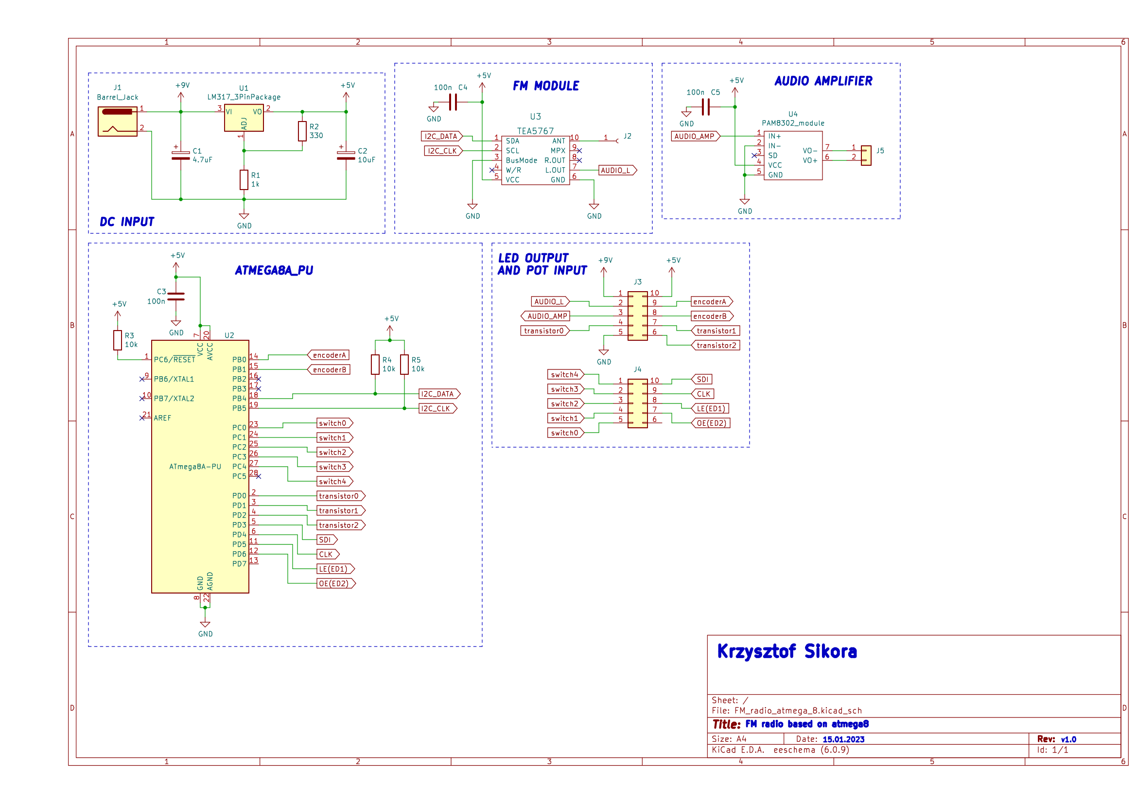
- main_radio_board - this one contains an Atmega8 microcontroller, TEA5767 FM radio module, PAM8302 amplifier module and power connector.
- display_and_controls_board - this one is specificly designed to fit in an old Unitra radio case, it has LEDs used as radio frequency indicators, rotary encoder for changing the frequency, potentiometer for volume and some additional buttons.
Radio board
My FM radio is based on the TEA7567 module, that is connected to an Atmega8A-PU microconotroller via I2C. Then it’s output goes to the connector, then on the main panel passes through a logarithmic potentiometer for volume control and comes back to the PAM8302 D-class amplifier module. I chose it because it works well with my speaker, which is the one used in the original Unitra radio (it is probably over 40 years old and still works very well).
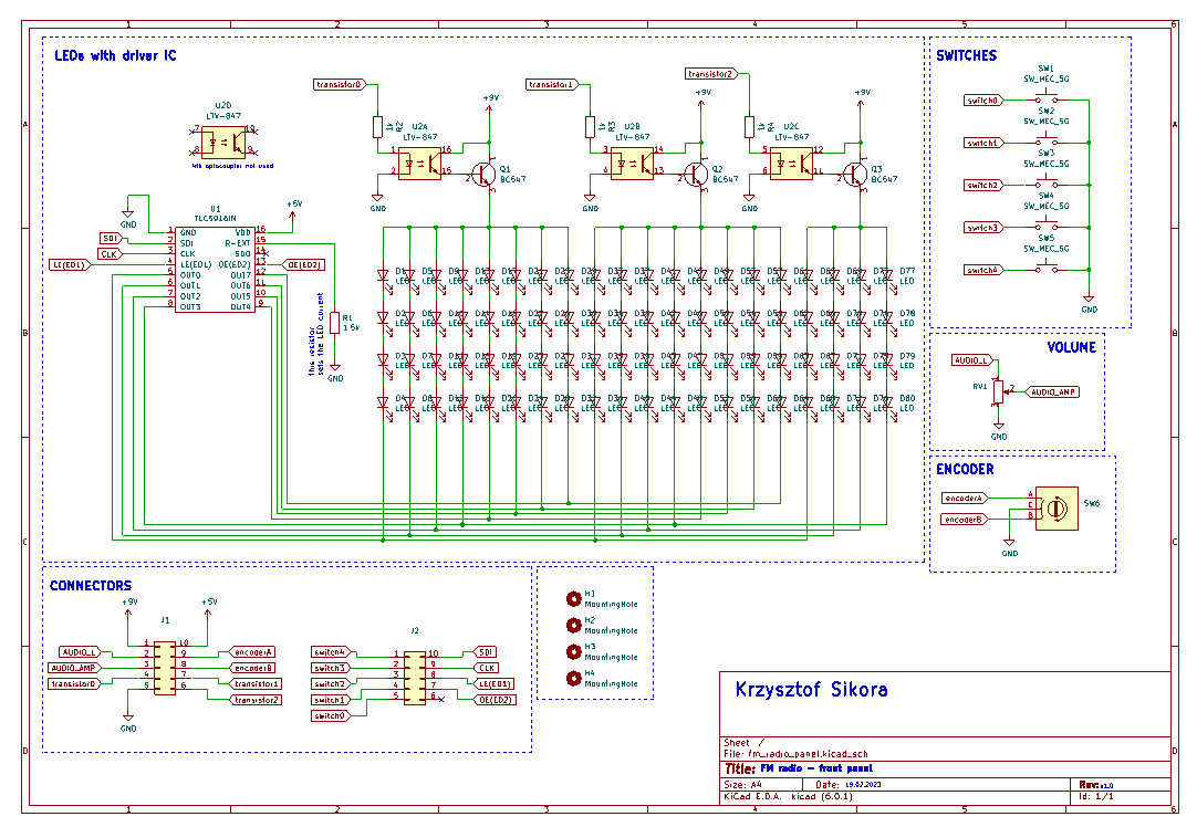
Schematic
The schematic and PCB were both designed using KiCAD 6.0
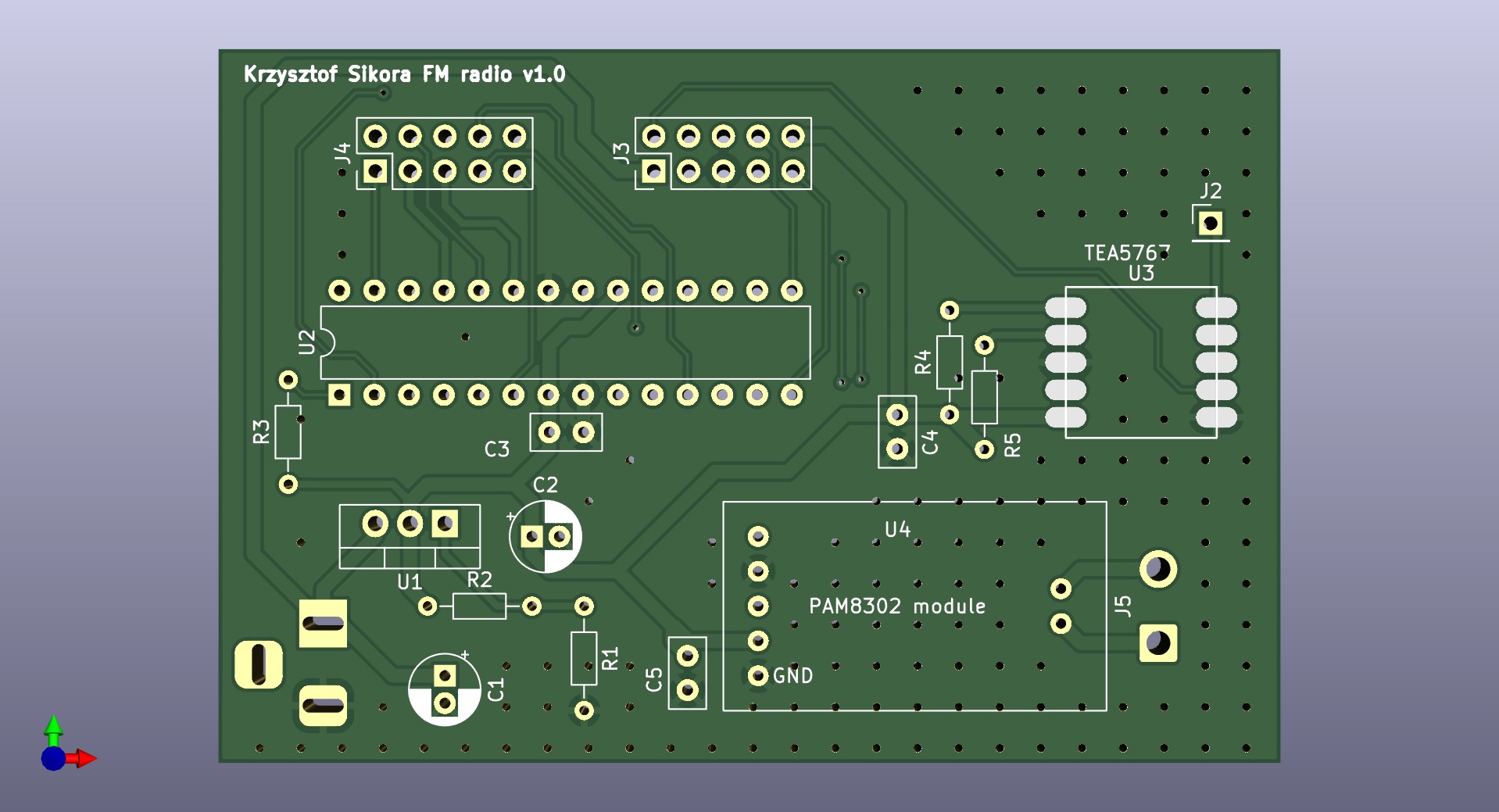
PCB design
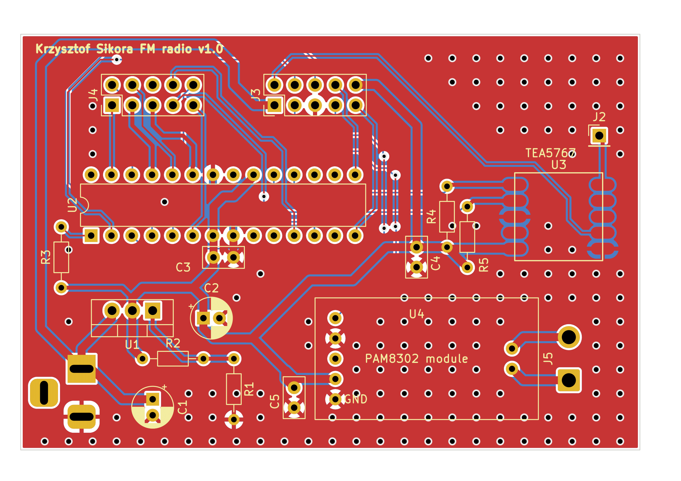
Connector pins
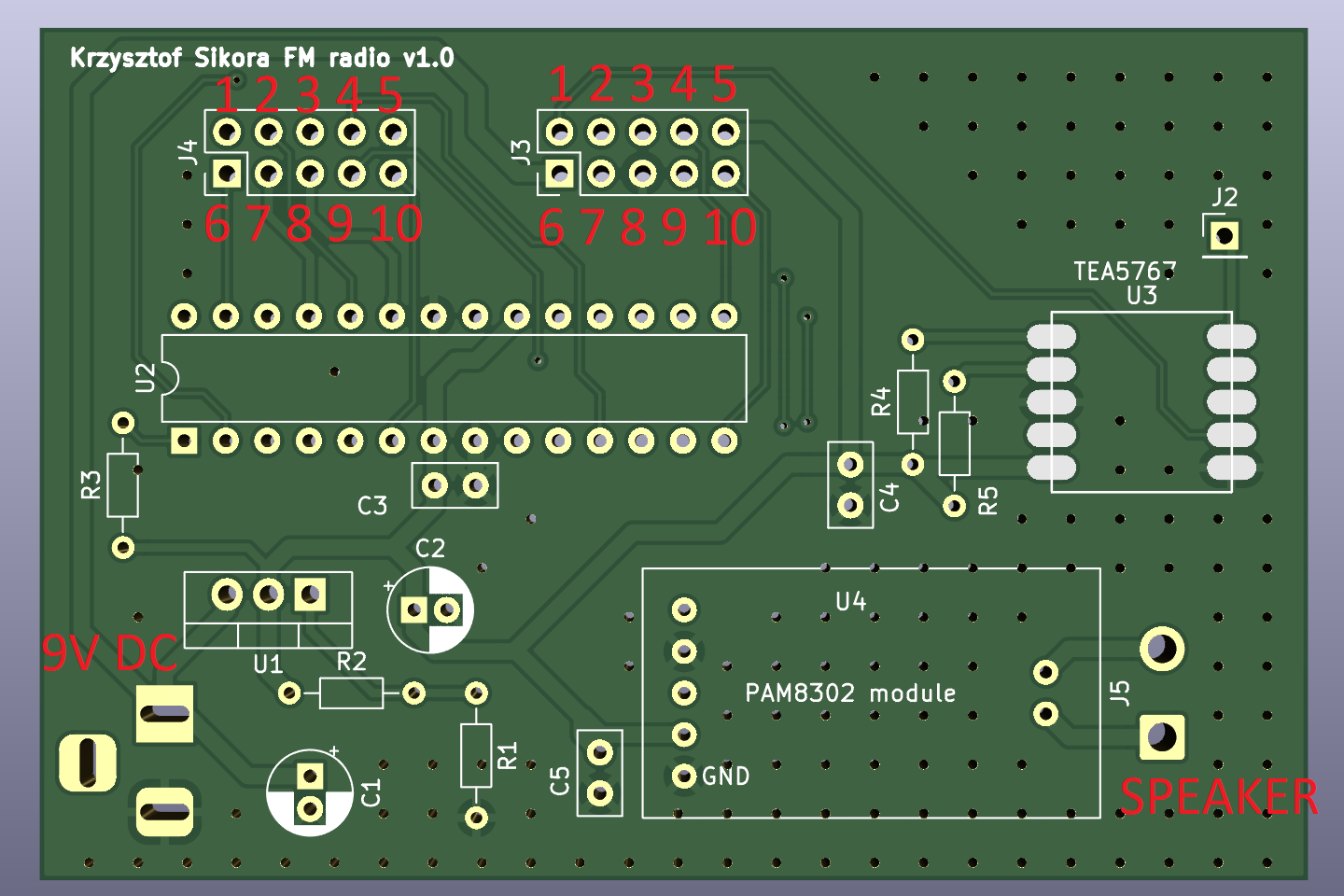
In the image above you can see the 9V DC input jack location, the speaker output connector and two pin headers (IDC connectors).
J4 connector pinout (all of these are generic GPIO pins of the Atmega8):
- 1 - switch 3
- 2 - switch 1
- 3 - NC
- 4 - LE(ED1)
- 5 - SDI
- 6 - switch 4
- 7 - switch 2
- 8 - switch 0
- 9 - OE(ED2)
- 10 - CLK
J3 connector pinout:
- 1 - TEA5767 output (to potentiometer)
- 2 - transistor 0
- 3 - transistor 2
- 4 - encoder B
- 5 - 5V DC
- 6 - 9V DC
- 7 - PAM8302 input (from potentiometer)
- 8 - GND
- 9 - transistor 1
- 10 - encoder A
Atmega8 code
The code is split into several files, you can find them all on my github.
- encoder.c - containing functions for interfacing with the rotary encoder
- i2c_lib.c - bit banging i2c library
- led_screen.c - functions for interfacing with led driver
- tea5767.c - functions for the TEA5767 FM radio module
- main.c - main program
Main function for the tea5767 is the send_freq function that tells the module to set a certain frequency:
void send_freq()
{
	unsigned char frequencyH;
	unsigned char frequencyL;
	unsigned int frequencyB;

	frequencyB = 4 * (frequency * 1000000 + 225000) / 32768;
	frequencyH = frequencyB >> 8;
	frequencyL = frequencyB & 0xFF;

    //data transmition
    I2C_Start();
	I2C_Write(TEA5767_ADDRESS_W);
	I2C_Write(frequencyH);
	I2C_Write(frequencyL);
	I2C_Write(0xB0);
	I2C_Write(0x10);
	I2C_Write(0x00);
    I2C_Stop();

    _delay_ms(10);
}
and the search function:
void search(uint8_t direction)
{
	unsigned char frequencyH;
	unsigned char frequencyL;
	unsigned int frequencyB;
    double temp = 88.0;

    if(direction == 1)
    {
        temp = frequency + 0.1;
    }
    else
    {
        temp = frequency - 0.1;
    }

	frequencyB = 4 * (temp * 1000000 + 225000) / 32768;
	frequencyH = frequencyB >> 8;
	frequencyL = frequencyB & 0xFF;

    I2C_Start();
	I2C_Write(TEA5767_ADDRESS_W); //send address for writing
	I2C_Write(frequencyH |= 0b01000000); //search mode
	I2C_Write(frequencyL);
    if(direction == 1)
    {
        I2C_Write(0b11010000); //search up with mid adc
    }
    else
    {
        I2C_Write(0b01010000); //search down with mid adc
    }
	I2C_Write(0x10);
	I2C_Write(0x00);

    I2C_Stop();

    _delay_ms(10);
}
You can find what the specific bytes being sent to the module mean in its datasheet.
In the main program loop we check the encoder status:
if(val != val_tmp)
{
    if( (val == 3 && val_tmp == 1) || (val == 0 && val_tmp == 2) )
    {
        if(frequency < 108.0)
        {
            frequency += 1.0;
            send_freq();
            display(frequency); //display the current frequency
            search(1); //search up from the set freq
        }
    }
    else if( (val == 2 && val_tmp == 0) || (val == 1 && val_tmp == 3) )
    {
        if(frequency > 88.0)
        {
            frequency -= 1.0;
            send_freq();
            display(frequency); //display the current frequency
            search(0); //search down from the set freq
        }
    }
}
and change the frequency by 1Hz, then search up from that frequency to fine tune the radio automatically.
In addition to that there are also button inputs:
if(bit_is_clear(button_1_port, button_1_pin))
{
    _delay_ms(15); //debounce
    if(bit_is_clear(button_1_port, button_1_pin))
    {
        search(1);
        _delay_ms(500);
        read_freq();
        display(frequency); //display the current frequency
    }
}
after pressing the button, the module starts an up search from the current frequency. Same aplies to the search down. You can also change the frequency to one from the predefined tabel by pressing button number 4 or 5.
Parts used
As it was just a revision of an older schematic, I did not bother to try and redesign it with newer uC etc. I just used the parts from the previous version (soldered onto a prototype board) or those I had lying around. Because of that the design may look a bit peculiar and I decided not to make a BOM file for it. Let me just list them in here for you:
- Atmega8A-PU microcontroller
- TEA5767 module
- PAM8302 amplifier module
- 2x IDC connector for the front panel
- LM317 for power step-down
- 9V DC jack input
- 3x ceramic 100nF capacitor
- 10uF and 4.7uF electrolytic capacitors
- 3x 10k resistor
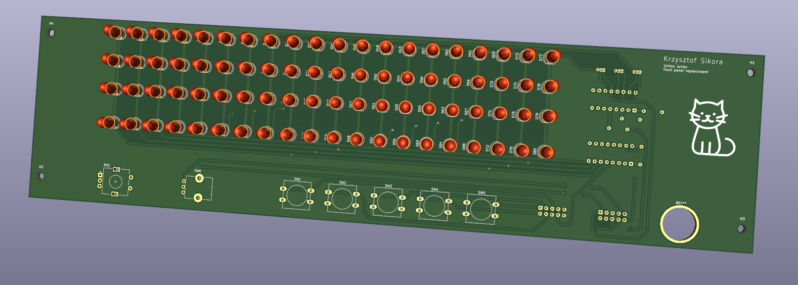
Front panel board
This board is used as my front panel for controls and displaying the current frequency etc.
Schematic
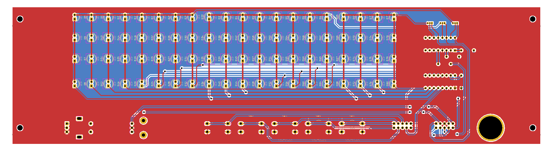
PCB design
Parts used
- LTV847 optocoupler
- TLC5916IN LED driver
- 3x 1kOhm resistor
- 1.5kOhm resistor
- 5x tact switch
- logarithmic potentiometer for audio control
- rotary encoder
- 2x IDC connector
- a lot of LEDs (red)
Author
Krzysztof Sikora
Cracow, 01.2023